Dongle Manual v1.0
Contents
NOTICE
The pic does NOT come pre-programmed from Microchip or any supplier. If you don't have a programmer then please see this wiki page for a list of folks who can program the pic for you.
Introduction
Thank you for making the decision to build the LYNX DMX DONGLE. I believe this decision will be one you will be very happy with. The Lynx is my attempt to design the best DMX dongle I could, at the lowest price I could, and make it available for the do-it-yourselfers like you. The goals for the dongle were professional looks and operation, cost effectiveness and ease of assembly for even a novice builder.
WARNING! This device has been designed for personal use as a means of education and entertainment. As such it is not rated, tested, or approved for use in commercial environments and such use is forbidden by the designer. Improper use of this equipment could be hazardous to life and property and the suitability of use is your responsibility. I assume no responsibility in the use or operation of this equipment or for the accuracy of any information made on part of itself. This device has been designed for my use and my use only. This is simply an explanation of how I built my own personal dimmers for informational purposes. I make no warranties written or otherwise to it. It should be considered an experimental device with possible unknown characteristics.
Before we start assembly of the LYNX DMX DONGLE, use the list on the next page to verify you have the correct parts and quantity of parts before we go any further. Please use static electricity precautions in the handling of these parts (ground straps, etc.). If you are not familiar with them please research on the Internet prior to handling them. You can damage your parts with improper handling!
Preparing to Build
The next thing we want is to make sure you are up to speed on soldering and electrostatic protection of the components in your kit. If you are not an experienced printed circuit builder, visit the site: http://curiousinventor.com/guides/How_To_Solder
And check out there extremely good video on soldering correctly. Even if you are an expert it is a good video to watch.
Another issue you must be aware of is that some electronic components can be damaged easily by electrostatic charges that can build up in you or your equipment. We have all been shocked by walking on carpet and grabbing a doorknob. This is electrostatic charge in action. It takes much less than this to hurt some of the parts. If you are unfamiliar with procedures to protect from this, please use the Internet to research it before opening your parts up. You can damage your parts with improper handling!
You will need a few tools build the LYNX DONGLE. You will need a good soldering iron. I cannot stress enough that a good soldering iron makes a big difference in these projects. The little 15w cheap irons are more apt to hurt your parts by taking too long to get the parts up to soldering temperature than a good iron which can bring it up to temp very fast. Remember, damage is a factor more in how long you keep the part hot than it is how hot you get it (within reasonable soldering temperatures). A good soldering iron is reasonable: You can purchase one for $30 to $60. Most any product that calls itself a soldering station that includes a temperature control separate from the iron itself will more than likely be fine, but make sure it is rated for more than 15 watts. I use a cheap Weller like this one
http://www.amazon.com/Weller-Soldering-Station-WLC100-120V/dp/B000ICEMYA
It works fine and is very inexpensive. I even saw this model on sale at Sears. Radio Shack has a very nice looking digital model on sale but be careful: it does not allow you to replace the tip. Tips are a part that wear out and need to replace them from time to time. While we are on the topic of tips, get some. I recommend you get the smaller chisel shape as this works very well for all-around board building.
You need solder, so buy some. I recommend .032 size as the larger sizes tend to cause you to put too much solder on. How much? Go ahead and get a 1 lb spool as it’s cheaper in large volume and you will go through it faster than you think. Make sure you are getting rosin core for electronics; they make some solder for plumbing that has acid as the core and this is a bad mistake to make.
You need some work area to work with good lighting. Do not attempt to solder circuit boards in poorly lighted areas. If you wear reading glasses, go get them: you will want them I promise you. I recommend a set of helping hands like this: http://www.radioshack.com/product/index.jsp?productId=2104639&cp=&parentPage=search
STEP 1
STEP 2
STEP 3
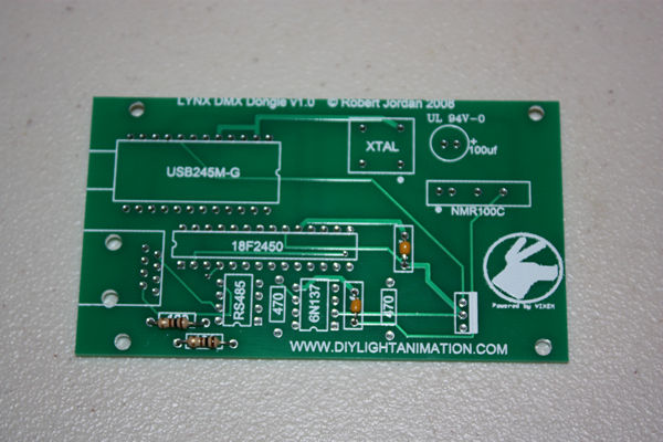
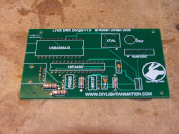
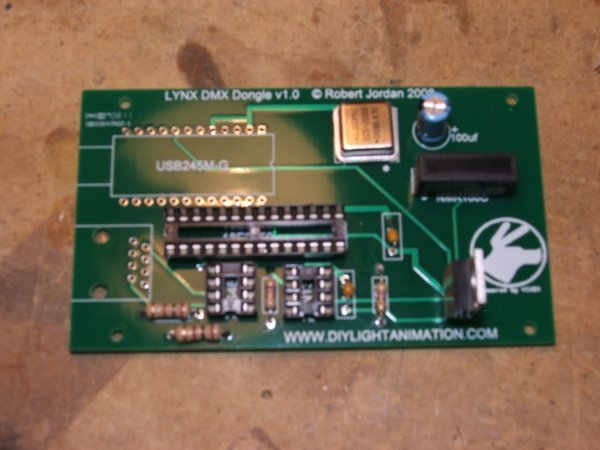
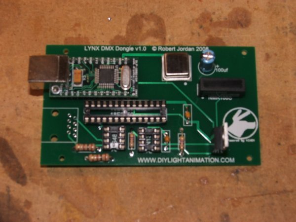
Install DIP sockets (571-1-390261-2 [4]), aligning them so the notches on the sockets match those on the board. This indicates the #1 pin end of the socket.
Next install the pic socket(571-1-390261-9 [5]), making sure the flat metal is on the side with the white solid rectangle of the board.
Now install the clock chip (520-TCH4000-X [6]), which is the shiny square. Make sure the small back dot is in the right bottom closest to the white dot on the PCB.
Install the DC to DC isolated power supply (580-MER1S0505SC [7]). Make sure that the pin #1 is on the end with the white dot. You cannot install it backwards; due to the pin alignment.
Install the 100uf capacitor (140-XRL25V100-RC [8]) and make sure the black strip is on the opposite side from the “+” on the PCB.
Install the Mosfet transistor (512-FQP27P06 [9]). Follow the markings on the silk screen, the metal side faces to the right.
STEP 4
Install the USB module (626-DLP-USB245M-G [10]) as pictured. Do not install a socket on this device: it must be soldered to the PCB directly.
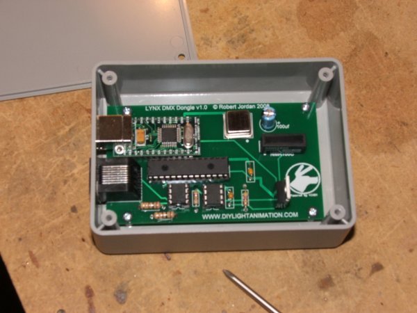
Solder the RJ45 jack (571-5202514 [11]) in place. (Shown in the next picture.)
MAKE SURE BOTH OF THESE ARE FLAT AND TIGHT AGAINST THE PCB WHEN YOU SOLDER IT.
STEP 5
Install the three chips making sure to take your time and not bend the pins. The notches on the chips should be on the same end as the notches on the sockets.
Referencing the picture in Step 1 to insert the RS485 chip (511-ST485BN [12]) in the socket on the left-hand side. The Optocoupler chip (630-6N137-000E [13]) will insert in the right-hand side socket.
Download the Hex file from the forum and program the PIC chip (579-PIC18F2450-I/SP [14]) with it using whatever steps are correct with your programmer.
Check out this post for a helpful .pdf: http://diylightanimation.com/index.php?topic=1395.msg14012#msg14012
Some helpful tips: http://www.youtube.com/watch?v=EOWWKPPilI0
They are not all facing the same way.
Make the two square holes in the case and mount the PCB into it.
STEP 6
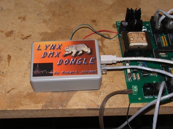
Screw the top on and flip the case over to the smooth side and attach the sticker.
Congrats! You have a DMX dongle. To download drivers go to http://www.ftdichip.com/Drivers/VCP.htm
and download and run http://www.ftdichip.com/Drivers/CDM/CDM%202.04.16.exe
Do not plug in the dongle until you have the drivers installed.
Now plug the dongle into a USB port on your computer using a USB cable and it should be found and installed as a comm port.
Go into Vixen and open a new sequence. Set up using the ENTTEC DMX PRO plug-in and assign it to the comm port the dongle created. Set the comm speed to 115K and exit the plug-in setup.
Now create some stuff and run it. You should have DMX coming out of the dongle. It’s that simple or so we hope.
I truly hope you enjoy your LYNX DMX DONGLE.
