FM Transmitters
Contents
General Information
| Legal Familiarization | To do anything contrary to FCC rules is at WHOEVER YOU ARE's own responsibility and that the information provided is for educational purposes and that DIYLIGHTANIMATION is not responsible for anything you do illegally.
We should only be transmiting a clear locked signal no more than 400 - 500 feet (aprox. 160 yards); any more than that is pushing it. The FCC will have no mercy busting you if you are hanging antennas up on the house or out in the yard and transmitting a strong signal more than 160 yards with FM transmitters pushing 0.5 or more watts beyond the threshold or interfering with licensed stations; even if you are doing it for Christmas. (See Technical Discusson Paper on how this was determined) Additionally, even though FM antennas should be kept out of site and in the house, that alone will not guarantee you are not illegally transmitting. It is your responsibility to keep our hobby from becoming the new FCC target. FCC References: FCC PDF Understanding FCC Regulations For Low-Power Non-Licensed Transmitters |
| Find a Open Frequency | U.S. light-show masters should always visit
before setting up their transmitter. You input your ZIP code and it tells you the three or four frequencies that work the best in your area. |
Recommended Transmitters by DLA Members (not DLA administration)
In No particular order
Not Recommended Transmitters
- Whole House Transmitters
- Belkin Ipod
Antenna’s & Frequency only
For those who are interested (you should attempt to read this) on the technical extrapolations of how I figured this all out, please read the Technical Discussion Paper.
Types of Antenna
Here are some common antennas (1/4 Wave Ground Plane, Rubber Ducky and 1/2 Wave Dipole are the only antennas recommended) the others are for reference only and should not be used in our situation.
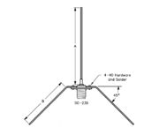
| 1/4 Wave Ground Plane: Of the different types of antennas, the quarter-wave has the least amount of gain. The quarter-wave does nothing to boost the received signal and should be used where the signal strength is sufficiently strong. This is the perfect type of antenna for our Low Power FM transmitted light shows, we don’t need to strengthen our transmission; we simply need good clean transmission.
The 1/4 Wave Ground Plane antenna is probably the easiest to build and least complex of the antennas. The quarter wave antenna has an omnidirectional pattern; it radiates equally well in all directions. This type of radiation pattern is preferred in mobile applications as the bearing from the device to the reciever is unknown or randomly changing. The quarter-wave antenna is well suited in fixed applications having a good ground plane and adequate signal strength. The quarter-wave requires a ground plane to work properly. A ground plane is a flat surface designed to limit the downward radiation of the antenna, and is generally 4 grounded piece of metal wire bent at 45 degree angles. If a 1/4 wave antenna is used without a sufficient ground plane, two things will happen: (1) Radiated power will tend to go out equally in all directions. Up and down as well as towards the horizon. Because your desired audience is not flying around the clouds, or digging tunnels in the ground, energy is wasted which would be better used transmitting toward the receiver audience in their cars. We don't want to be transmitting or interfering with our aviation friends as that would upset the FCC. (2) An improperly installed quarter-wave antenna does not establish a good reference plane for the radiating field. When this happens, the antenna is said to be mismatched and the transmitter will see a high SWR (Standing Wave Ratio). Much of the power that the transmitter generates will then bounce back into the transmitter and be dissipated as heat causing damage to your nice FM transmitter. This reduces the signal that the audience receives and may cause improper decoding in fringe areas, along with spurious emissions. LOTS OF NOISE. | |
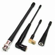
| Flexible dummy loads (often called Rubber Ducky, or a Loaded Vertical): Probably the first, least expensive step is the replacement of the stock, dummy load antenna that the unit came equipped with. Almost anything more should and will improve your FM music quality and range. Even a wet string, cut to the right length will work better. These antennas (with your FM transmitter) are loaded so you cannot transmit very far. They simply provide the ability for you to use your FM transmitter as soon as you get it in the mail.
Amazingly, there is a trick to make them work better. Most people do not know how, but I will give away the secret. An expedient often improves performance of your flexible antenna and is a wire counterpoise that is an 18" piece of wire for VHF FM frequencies. A counterpoise prevents transmitted RF from coupling with your body or other surrounding elements. Your antenna now performs like a center-fed dipole (See Dipole), instead of an "end-fed dummy load!" Simply cut some AWG18-22 Gage, insulated wire to 18 inches, crimped and then soldered to alligator style battery clip, which will fit over the outer shield of a the BNC connector on the antenna. This will make a huge improvement that will amaze you. | |
| The Dipole: A dipole antenna is a straight electrical conductor measuring 1/2 wavelength from end to end and connected at the center to a radio-frequency (RF) feed line. This antenna, also called a doublet, is one of the simplest types of antenna, and constitutes the main RF radiating and receiving element in various sophisticated types of antennas. The dipole is inherently a balanced antenna, because it is bilaterally symmetrical. Because this is a half-wave antenna, it will exhibit gain over a quarter-wave ground-plane antenna and we, as FCC restriced FMer's, really don't need any Gain to our tranmission.
Ideally, a dipole antenna is fed with a balanced, parallel-wire RF transmission line. However, this type of line is not common for our FM transmitters. An unbalanced feed line, such as coaxial cable, can be used, but to ensure optimum RF current distribution on the antenna element and in the feed line, an RF transformer called a balun (contraction of the words "balanced" and "unbalanced") should be inserted in the system at the point where the feed line joins the antenna. This is where it gets complicated and because of this, I would stick with using the 1/4 wave antenna. For best performance, a dipole antenna should be more than 1/2 wavelength above the ground, the surface of a body of water, or other horizontal conducting medium such as sheet metal roofing (another issue with this antenna because it would require outside installation and we don’t want to do that). The element should also be at least several wavelengths away from electrically conducting obstructions such as supporting towers, utility wires, guy wires, and other antennas; even more issues that are inherent with this antenna. | |
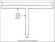
| The Folded Dipole: A folded dipole is a dipole antenna with the ends folded back around and connected to each other, forming a loop. This antenna would not be easily matched to your FM transmitter but is perfect for your FM receivers. For this reason and the complexities that occur during transmission, I would highly recommend you not attempt using this kind of system for your light show. Enough said. | |
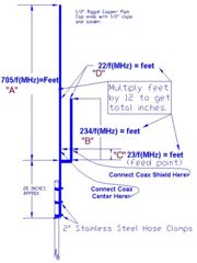
| J-Pole: The J-pole antenna, also called the Zepp' antenna (short for Zeppelin), was first invented by the Germans for use in their lighter-than-air balloons. Trailed behind the airship, it consisted of a single element, one half wavelength long. This was later modified into the J-pole configuration, which became popular with amateur radio operators because it is effective and relatively simple to build.
The J-pole antenna is an end-fed omnidirectional dipole antenna that is matched to the feedline by a quarter wave transmission line stub. Matching to the feed-line is achieved by sliding the connection of the feedline back and forth along the stub until a VSWR as close as possible to 1:1 is obtained. Because this is a half-wave antenna, it will exhibit gain over a quarter-wave ground-plane antenna. The J-pole is somewhat sensitive to surrounding metal objects, and should have at least a quarter wavelength of free space around it. This is another complicated fixture and adding any gain to our FM transmitters is not the direction the FCC would like us to go. For these reasons, I do not recommend using this system. | |
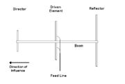
| Multiple Element Yagi Beam: The word "Yagi" is used to describe a type of antenna and is credited to very famous Japanese antenna experts by the names of Yagi and Uda! Most ham radio enthusiasts refer to this type of antenna as the "Yagi" rather than use both men's names.
They discovered that by adding "elements"of various lengths and spacings in front of and behind a dipole antenna that the performance and effectiveness of the dipole could be greatly increased and the pattern of the dipole RF energy could be "beamed" or focused in one direction, with the resulting "effect" of making it appear that the transmitter was running lots more power than it actually was, yielding much stronger signals both on receive and transmit! Do we need to go any further here? This antenna looks like the old TV antenna and is way more complicated than we need and we certainly don’t need to beam our music across town. Lets move on. |
There are more, but the one’s I’ve listed are the more popular antennas used.
Benefits to proper antenna matching
The single most important component affecting reception quality of your audience is the receiver antenna (the folks that drive by) and the single most important component of transmitting quality is your FM transmitter to antenna match. If your FM transmitter has the capability of producing a certain transmitted quality of sound (MUSIC) and you don't have a matched transmitter to antenna, then the quality of your MUSIC will be lost. There is nothing you can do to improve MUSIC quality if your delivery system is not TUNED and PROTECTED from what it does to itself.
Actually, the antenna can be a major source of interference. If the length of the antenna is not properly matched to the transmitter, it can and will generate unwanted signals that are transmitted more effectively than the desired operating frequency and your music.
We don't need distance, we need quality. Let me give a practical example.
Let's imagine you have a 500 Watt stereo amplifier (FM Transmitter) and you decide to hook up a set of $5 speakers (Your Rubber Duck Antenna) to your system. Your neighbor has a 2 Watt stereo amplifier with a set of $500 speakers. I can assure you the 500 watt system will overdrive the $5 speakers and it will sound like crap. On the other side of the street, the 2 watt amplifier with those great speakers will sound much better no matter what volume it is set at. That is exactly what we want, Low Watt, High Quality transmission.
We don't need power to get great sound at reasonable distances. If we do have high power, plus a great antenna system we can adjust it down with attenuation and get the short range with great transmitted sound we want.
In any event, as you can see, the delivery system, speakers in the example, the antenna in our FM transmitter, is the key. Nothing has more impact on quality than the delivery system. Sure, we can put all kinds of equipment that enhances sound quality in-between, but with junk for delivery, you'll have little if any better quality reaching your audience.
Easy To Build Antennas
There are only two antennas listed that are easy to build and they are:
1. 1/4 Wave Ground Plane
2. 1/2 Wave Dipole
The Rubber Ducky antenna can easily be modified to produce amazingly good results.
You may ask, why would I want to build my own antenna when I can just go buy one? Well, simply put, we are Do-It-Yourselfers, so why not, and because it's easier than what you already do with lights and controllers. Another way to look at it would be the more you know about what you're doing the better show you can produce. Also, I'm not only going to show you how to build one, I'll show you how to reduce the risk of over transmitting and getting into trouble with the FCC whether you build your own or go buy one.
Our goal is to make blinky blink sound good in a short distance using FM transmitters. A lot of folks have their own understanding about what the FCC's Public Notice, Part 15 of FCC law (put link here) means. Before we start building, let me try to explain what I interpret from it.
In that document it states for "Unlicensed Operation, PART 15 of FCC rules" Aproxi. Maximum Coverage Radius of 200 feet in the FM column. In that same column it reads 0.01 micro-watts measured at 3 meters, that's one millionth of 1 watt, measured at 9.8 feet "FROM THE ANTENNA" for Maximum Effective Radiated Power. The rule actually specifies a limit of 250 micro volts per meter at 3 meters (aprox. 9.8 feet).
What does that mean to us? For one, that does not mean your FM transmission FROM YOUR ANTENNA must stop at 200 feet and that if your music is transmitted over 201 feet; you're busted. Secondly, it does not mean you can't use a transmitter that has more power than 1 millionth of a watt. Thirdly, it does not mean you cannot build and use your own antenna on the FM Kit you purchased outside or inside the USA you built or assembled on your own. If your transmitter is not Certified FCC Part 15, then you must make every attempt to comply with the restrictions of Low-Power, Non-Licensed Transmitters. Of all the confusion in that document, the one thing that makes any sense is the 250 micro volts at 3 meters. Everything else is confusing. Simply put, if you take an RF Meter at 3 meters (9.8 ft) from your antenna, the transmission energy from it should not exceed 250 micro volts. Media:FM_TRANSMITTER_TECHNICAL_PAPER.pdf Technical Discussion Paper
However, the FCC do have restrictions for Part 15 Compliant Transmitters certified as such. If your Transmitter is certified as FCC Part 15 compliant, the manufacturer must have a permanently attached antenna, or detachable antenna with unique connectors. A "unique connector" is one that is not of a standard type found in electronic supply stores. If you proceed to make and install the following antennas, or modify the one on your FCC Part 15 Certified rig in any way, your Certified Part 15 Transmitter will no longer be Certified as compliant. You can still use it, just be aware it's certification is invalid and you still have to comply with the law.
Let's Build a 1/4 Wave Ground Plane Media:DIY_Quarter_Wave_Antenna.pdf
Let's Build a 1/2 Wave Dipole Coming Soon...
Let's Turn That Rubber Ducky Into A Golden Eagle Coming Soon...
What not to do's
1. Don't broadcast your show without determining how far you are actually transmitting. Your shows transmission should be dropping off the air at around 500 ft (aprox. 160 Yards) FROM YOUR ANTENNA; any further and you could be subject to FCC retaliation. See (Technical Discussion Paper) on how I figured this out.
2. Don't mount your antenna up on the roof or on a pole out in your yard. Why? Doing so may create a situation where you are transmitting too far. It will also draw attention to the "Men In Black" if you are causing interference and they get a complaint. Besides, you can't put lights on your antenna :-)
3. Do not transmit over a station that is licensed to use the same frequency, your neighbors will complain and you are subject to a fine from the FCC, even if you are within the legal range to transmit. We have absolutely no rights to interfere with licensed stations. Doing so is the single most guaranteed reason the FCC will track you down and FINE YOU.
4. Please, do not think just because a manufacturer or distributor claims the transmitter sold to you is FCC Part 15 compliant that it actually is. There are four important things that must be true to the transmitter and it's matching antenna you receive. If any of the following are "NOT" true, your rig is not really Certified as FCC Part 15 compliant, even if the provider says it is. With the exception of measured transmission energy at a distanc of 3 meters (9.8 ft); they are:
(1) FCC Part 15.203 states that intentional radiators operating under this rule shall be designed so that no antenna other than that furnished with it by the responsible party shall be used with the device.
(2) The second option is that the antenna be professionally installed. FCC's definition of professional installation had been somewhat ambiguous. For the most part, however, high-gain antennas designed to be mounted on a building exterior or a mast generally fall under the professional-installation clause. (The definition of professional installer does not include your brother-in-law simply because he can work the VCR remote or plug in the DVD player.)
(3) The third option allows a nonstandard or unique connector to secure the antenna to the transmitter. If the connector is available at Radio Shack, then it is not considered unique.
(4) The product you've been sold has an FCC ID.
That's pretty much it. I hope everyone is clear that we can make our own antennas, and we can build our own FM transmitters and use them without breaking the law. The more you know about what you are really doing the easier it is to do it right.
My intension was not to scare you away from doing what we love to do. It was to help protect you from becoming a victim of ignorance. We can easily be fooled into thinking that what we built or bought is FCC PART 15 compliant, when it really isn't. The important thing to remember is when you walk 160 yards away from your antenna and you are tuned to your Christmas FM station (ideally) is that what you hear is something not coming from your antenna. If you can achieve that, then you will be very pleased and worry free of your show.
I hope you got something out of this, and always remember... You are the one who intentionally turns on the transmitter and that's all that matters to the FCC when they get a call or complaint; not the source from which you acquired your system.
Good luck and be safe...
FCC References:
Media:FCC-DA-00-1087.pdf FCC Public Notice DA 00-1087, Federal Communications Commission, May 22, 2000
Media:DA-00-1407A1.pdf FCC Public Notice DA 00-1407, Federal Communications Commission, June 26, 2000
Other References And Technical Documents:
Media:FM_TRANSMITTER_TECHNICAL_PAPER.pdf Technical Discussion Paper
