Difference between revisions of "Manual MR16"
(→STEP 1) |
(v2 done by mokeefe) |
||
| (12 intermediate revisions by 2 users not shown) | |||
| Line 2: | Line 2: | ||
| − | [[Image:MR16- | + | [[Image:MR16-2-16.JPG|800px|Thumb]] |
| Line 15: | Line 15: | ||
| − | + | Case - Keptel CG-500 | |
| − | + | = Preparing to Build = | |
| − | + | The next thing we want is to make sure you are up to speed on soldering and electrostatic protection of the components in your kit. If you are not an experienced printed circuit builder I recommend you visit the site: | |
| − | + | ||
| − | + | ||
| − | + | [http://curiousinventor.com/guides/How_To_Solder http://curiousinventor.com/guides/How_To_Solder] | |
| − | + | ||
| − | + | ||
| − | + | ||
| − | + | And check out its extremely good video on soldering correctly. Even if you are an expert it is a good video to watch. | |
| − | + | ||
| − | + | ||
| − | + | ||
| − | |||
| − | |||
| − | |||
| − | |||
| − | + | Another issue of which you must be aware: some electronic components can be damaged easily by electrostatic charges which can build up in you or your equipment. For example, we have all been shocked by walking on carpet and grabbing a door knob. This is an electrostatic charge in action. It takes much less than this to hurt some of our parts. If you are unfamiliar with procedures to protect from this please use the Internet to research it before taking your parts out of their packaging. '''You can damage your parts if handled incorrectly! ''' | |
| − | + | ||
| − | + | ||
| − | + | ||
| − | |||
| − | |||
| − | |||
| − | |||
| − | + | You will need a few tools that do not come with your kit to build the MR-16. You will need a good soldering iron. I cannot stress enough that a good soldering iron makes a big difference in these projects. The little 15w cheap irons are more apt to hurt your parts by taking too long to get them up to soldering temperature than a good iron which can bring it up to temp very fast. Remember, damage is more about how long you keep the part hot than it is how hot you get it (within reasonable soldering temperatures). A good soldering iron can be had reasonably. You can purchase one for $30 to $60. Most anything that is called a soldering station -- where there is a temperature control separate from the iron itself -- will more than likely be fine, but do make sure it is rated for more than 15 watts. I use a cheap Weller like this one | |
| − | + | ||
| − | + | ||
| − | + | ||
| − | + | [http://www.amazon.com/Weller-Soldering-Station-WLC100-120V/dp/B000ICEMYA http://www.amazon.com/Weller-Soldering-Station-WLC100-120V/dp/B000ICEMYA] | |
| − | + | ||
| − | + | ||
| − | + | ||
| − | + | It works fine and is inexpensive. I even saw this model on sale at Sears. Radio Shack has a very nice looking digital model on sale, but be careful as it does not allow you to replace the tip. Tips are a part that wear out and need replacing from time to time. While we are on tips: get some extras. I recommend you get the smaller chisel shape as these work very well for all-around board building. | |
| − | + | ||
| − | + | ||
| − | + | ||
| − | |||
| − | |||
| − | |||
| − | |||
| − | + | You need solder, so buy some. I recommend .032 size as the larger sizes tend to cause you to put too much solder on. How much? Go ahead and get a 1 lb. spool, as it’s cheaper in large volume and you will go through it faster than you think. Make sure you are getting rosin core for electronics; they make some solder for plumbing that has acid as the core (this is a bad mistake to make). | |
| − | + | ||
| − | + | ||
| − | + | ||
| − | |||
| − | |||
| − | |||
| − | |||
| − | + | You need some work area to work with good lighting. Do not attempt to solder circuit boards in poorly lighted areas. If you wear reading glasses, go get them -- you will want them I promise you. I recommend a set of helping hands like this: [http://www.radioshack.com/product/index.jsp?productId=3928375 http://www.radioshack.com/product/index.jsp?productId=3928375] | |
| − | + | ||
| − | + | ||
| − | + | ||
| − | + | = STEP 1 - Installing the Resistors and Ceramic Capacitors= | |
| − | + | ||
| − | + | ||
| − | + | ||
| − | |||
| − | |||
| − | |||
| − | |||
| − | + | [[Image:MR16-2-4.JPG|800px|Thumb|]] | |
| − | | | + | |
| − | | | + | |
| − | | | + | |
| − | |||
| − | |||
| − | |||
| − | |||
| − | + | Install the 4 0.1uF ceramic capacitors as marked (3 near the top and 1 in the middle right). The ceramic capacitors are not polarized so orientation does not matter. | |
| − | + | ||
| − | + | ||
| − | + | ||
| − | + | Install the 180 ohm (brown-gray-brown) resistor in the upper left corner. The orientation on all of the resistors does not matter, although you will end up with a cleaner looking build if you orient them in a consistent way. | |
| − | + | ||
| − | + | ||
| − | + | ||
| − | + | Install the 1K ohm (brown-black red) resistor below the area marked XTAL. | |
| − | + | ||
| − | + | ||
| − | + | ||
| − | + | Install the 120 ohm (brown-red-brown) resistor in the very upper middle area. | |
| − | |||
| − | + | '''If you are doing the standard build and will be using the MOSFET's for high current operation, install the following:''' | |
| − | + | ||
| − | + | Install the 16 3.0K ohm (orange-black-black-brown-brown) resistors in the marked locations across the middle of the PCB. | |
| − | + | Install the 16 0.1uF ceramic capacitors as marked (across the middle). | |
| + | Install the 4.7K ohm (yellow-violet-red) resistor in the location above the label "Current Limiter". | ||
| − | |||
| + | '''If, however, you plan to jumper where the ovals are marked and leave the MOSFET's off for constant current drive up to 100ma per channel, then:''' | ||
| − | + | Do '''NOT''' install the 16 3K resistor and 16 0.1uF capacitors. | |
| − | + | Choose a resistor to match the current limit you need and install it in place of the 4.7K ohm resistor. The correct value for the current needed can be located in the datasheet for the TLC5940NT chip. Common currents are: | |
| + | *20 ma - Use 1.91K ohm. | ||
| + | *100 ma - Use 380 ohm. | ||
| − | |||
| + | Solder and trim all excess leads. | ||
| − | |||
| + | '''That’s a lot of soldering so take a break'''. If you try to do too much in one sitting you will start making too many mistakes. Mistakes with soldering are costly in time. | ||
| − | |||
| − | = STEP | + | = STEP 2 - Installing the IC Sockets and Oscillator= |
| − | + | ||
| − | [[Image:MR16- | + | [[Image:MR16-2-6.JPG|800px|Thumb|]] |
| − | + | Install the 8 pin IC socket in the area labeled RS485. | |
| − | Install the | + | |
| − | + | Install the 18 pin IC socket in the area labeled 18F1220. | |
| − | + | Install the 28 pin IC socket in the area labeled TLC5940NT. | |
| − | + | Line up the notch on the sockets with the notched end of the drawings on the PCB and then solder all the pins. | |
| − | + | Some sockets now come with slightly contoured pins that hold them in place in the PCB prior to soldering. If you do not have this kind of socket you will want to use a method to hold it in place while soldering. Everyone has their own way of holding the socket in. I like to turn the board over to the back and put the least amount of solder I can over one of the middle holes on one side of the socket. This allows you to put the pins of the other side of the socket through and hold the socket while pushing extremely easy. Then you heat that one hole on the back. When the solder melts the socket will drop in. remove the iron and it will cool and hold the socket in until you are done. Make sure to reheat this pin while doing the others to insure you have a good joint. Some people prefer to use tape to hold them in and some even super glue them on first and then solder. If you use tape then the painter’s masking tape is a good option as it does not leave any residue behind when it is removed. Make sure your socket is in the correct holes and that it faces the correct way and then solder the other pins in. | |
| − | + | Locate the 40 MHz oscillator module. It is a shiny square unit with four pins. Install it in the area marked XTAL. The oscillator must also be oriented properly. You will notice a small dot on one corner of the component. This should line up with the white dot on the board. The corner with the dot will also have a square corner instead of rounded corners. Solder the four pins to the board. | |
| + | = STEP 3 - Installing the Spade Terminals= | ||
| − | |||
| + | [[Image:MR16-2-7.JPG|800px|Thumb|]] | ||
| − | |||
| − | + | Install the quick fit spade terminals. Push each spade terminal into the 32 locations across the bottom. Then install two for power on the right side of the PCB. Flip over the board and solder them. Make sure you have good solder connections here. | |
| − | Install | + | |
| + | = STEP 4 - Installing the RJ-45 Connectors, Jumper Headers, Electrolytic Capacitor= | ||
| − | |||
| − | + | [[Image:MR16-2-10.JPG|800px|Thumb|]] | |
| − | + | Install the 2 RJ-45 connectors in the locations at the top labeled DMX OUT and DMX IN. They will snap in tight so make sure to align the small pins correct and then support the board as you push them in. It takes effort to snap them in so support the PCB when you do this. Some like to put the PCB on foam and do it where the foam allows it to support the PCB. Solder the 8 pins on both sockets | |
| − | + | Install the round 100uf electrolytic capacitor. This capacitor is polarized and needs to be installed with the correct orientation. Make sure the black band marked “-“ is '''NOT''' on the side where the “+” is labeled on the board. | |
| − | + | Install the 2 pin and the 3 pin jumper headers at the top of the PCB in the area labeled Terminate DMX and Mode. | |
| + | Solder the capacitor and headers. Trim any excess leads. | ||
| − | + | You can store the two blue jumpers by slipping them onto one of the posts of each header. | |
| − | + | = STEP 5 - Installing the Red and Green LED's = | |
| − | + | [[Image:MR16-2-11.JPG|800px|Thumb|]] | |
| − | + | Install the red LED on the left side of the board below the PWR label. It is important to install the LED oriented properly. The LED will generally have one lead that is longer than the other. This is the positive (+) lead. The LED should be installed with the longer positive lead in the hole near the "+" label on the PCB. | |
| − | + | Install the green LED on the right side of the board below the DMX label. Be sure to orient it properly as above. | |
| − | Install | + | |
| + | Solder and trim the leads. | ||
| − | |||
| + | = STEP 6 - Installing the MOSFET's and Voltage Regulator= | ||
| + | [[Image:MR16-2-13.JPG|800px|Thumb|]] | ||
| − | |||
| + | '''If you will be doing the standard high current build:''' | ||
| − | Install the | + | Install the 16 MOSFET's across the middle of the board. Make sure and face the flat metal side of the MOSFET's toward the bold white rectangle side of the outline on the board (facing right). Do not confuse the 16 MOSFET's with the one 7805 voltage regulator as they look identical. |
| − | + | '''If, however, you are going to use it in constant current mode:''' | |
| + | Do '''NOT''' install the MOSFET's and, instead, install 16 jumpers in the areas that have the ovals around them. | ||
| − | |||
| − | |||
| − | + | Solder the MOSFET's or jumpers and trim the leads. | |
| + | Install the 7805 voltage regulator in the middle right section of the PCB. Make sure and face the flat metal side of it toward the white rectangle side of the part outline on the board (left facing). Solder and trim the leads. | ||
| + | = STEP 7 - Installing the Voltage Regulator Heat Sink= | ||
| − | |||
| − | + | [[Image:MR16-2-14.JPG|800px|Thumb|]] | |
| − | |||
| − | + | Install the metal heat sink onto the 7805 voltage regulator. It should be oriented so that the large flat side is facing left. Solder the two tabs of the heat sink. | |
| − | + | ||
| − | + | = STEP 8 - Installing the IC's = | |
| − | + | Install the TLC5940NT, 18F1220, and RS485 chips into their respective sockets. Make sure you align the notch on the end of the chip with the notch on the socket. Be very careful and do not bend any pins as they sometimes can be a challenge to insert straight. Take your time here and before pushing them in. Look over both sides to make sure all pins are started straight. | |
| − | + | '''Congratulations, you have a finished building the Lynx MR16 V2 Controller!''' | |
| − | |||
| − | |||
| + | You will need to feed the board from a regulated 7 to 24 volt DC power supply (12V is typical). Make sure the supply has the current capacity to handle the lights you are controlling. For example, the WireKAT 32 LED MR16 draw about .17 amps per lamp. Plan accordingly for your use. | ||
| − | |||
| + | Do not attempt to control more than 2.5 amps per channel from the MR16 controller. I also recommend you keep the total controller current under 35 amps if possible. | ||
| − | + | = Programming and Operation = | |
| − | + | '''Programming the MR-16''' | |
| − | + | The MR16 controller needs to be programmed for its starting DMX channel. This is the channel that output number 1 will be addressed by in the DMX data. If you want this controller to handle channels 80 through 95, for example, you would assign it the starting channel of 80. | |
| − | + | {{Set_Address}} | |
| − | + | It should now be set to operate on the channel you wanted. You can change it anytime and as often as you need. It will remember the address for at least 20 years with no power applied. | |
| − | + | '''Operation''' | |
| − | + | The MR16 is a DMX device and can be controlled from programs such as Vixen, Light-O-Rama, Light Show Pro, and others. | |
| − | + | When using Vixen I recommend you set Vixen to “draw at 255 levels” instead of 0-100 levels. This will give you access to all 256 levels it provides and not limit it to just 100 steps. | |
| − | + | To connect another DMX device to this one simply use a standard straight through Cat5 cable to go from the “DMX OUT” jack to the next device and connect it to its “DMX IN” jack. | |
| − | |||
| − | |||
| − | |||
| − | |||
| + | <center>'''REMEMBER ALWAYS HAVE IT POWERED OFF WHEN WORKING WITH IT. BE SAFE!'''</center> | ||
| − | + | *Original V1.0 Manual by RJ | |
| − | + | *Updated V2.0 Manual by mokeefe | |
| − | + | ||
Latest revision as of 18:20, 5 August 2012
Contents
- 1 Introduction
- 2 Preparing to Build
- 3 STEP 1 - Installing the Resistors and Ceramic Capacitors
- 4 STEP 2 - Installing the IC Sockets and Oscillator
- 5 STEP 3 - Installing the Spade Terminals
- 6 STEP 4 - Installing the RJ-45 Connectors, Jumper Headers, Electrolytic Capacitor
- 7 STEP 5 - Installing the Red and Green LED's
- 8 STEP 6 - Installing the MOSFET's and Voltage Regulator
- 9 STEP 7 - Installing the Voltage Regulator Heat Sink
- 10 STEP 8 - Installing the IC's
- 11 Programming and Operation
Introduction
Thank you for making the decision to build the LYNX MR16 Controller. I believe this decision will be one you will be very happy with. This controller was my attempt to design the best dimming controller for MR16 spot lights available for the do it yourselfer’s like you. The goals for the controller were professional looks and operation, cost effective, easy to assemble for even a novice builder, DMX compatible, software start channel programming.
WARNING! This device uses potentially deadly voltages in operation. If you do not feel it is within your ability to work with these voltages please stop and get assistance, or purchase ready built commercial dimmers. This dimmer has been design for personal use as a means of education and entertainment. As such it is not rated, tested, or approved for use in commercial environments and as such is forbidden by the designer. Improper use of this equipment could be hazardous to life and property and the suitability of use is your responsibility. I assume no responsibility in the use or operation of this equipment or for the accuracy of any information made on part of itself. This device has been design for my use and my use only. This is simply an explanation of how I built my own personal dimmers for informational purposes. I make no warranties written or otherwise to it. It should be considered an experimental device with possible unknown characteristics.
Please use static precautions in the handling of these parts. If you are not familiar in them please research on the internet prior to handling them. You can damage you parts with improper handling!
Case - Keptel CG-500
Preparing to Build
The next thing we want is to make sure you are up to speed on soldering and electrostatic protection of the components in your kit. If you are not an experienced printed circuit builder I recommend you visit the site:
http://curiousinventor.com/guides/How_To_Solder
And check out its extremely good video on soldering correctly. Even if you are an expert it is a good video to watch.
Another issue of which you must be aware: some electronic components can be damaged easily by electrostatic charges which can build up in you or your equipment. For example, we have all been shocked by walking on carpet and grabbing a door knob. This is an electrostatic charge in action. It takes much less than this to hurt some of our parts. If you are unfamiliar with procedures to protect from this please use the Internet to research it before taking your parts out of their packaging. You can damage your parts if handled incorrectly!
You will need a few tools that do not come with your kit to build the MR-16. You will need a good soldering iron. I cannot stress enough that a good soldering iron makes a big difference in these projects. The little 15w cheap irons are more apt to hurt your parts by taking too long to get them up to soldering temperature than a good iron which can bring it up to temp very fast. Remember, damage is more about how long you keep the part hot than it is how hot you get it (within reasonable soldering temperatures). A good soldering iron can be had reasonably. You can purchase one for $30 to $60. Most anything that is called a soldering station -- where there is a temperature control separate from the iron itself -- will more than likely be fine, but do make sure it is rated for more than 15 watts. I use a cheap Weller like this one
http://www.amazon.com/Weller-Soldering-Station-WLC100-120V/dp/B000ICEMYA
It works fine and is inexpensive. I even saw this model on sale at Sears. Radio Shack has a very nice looking digital model on sale, but be careful as it does not allow you to replace the tip. Tips are a part that wear out and need replacing from time to time. While we are on tips: get some extras. I recommend you get the smaller chisel shape as these work very well for all-around board building.
You need solder, so buy some. I recommend .032 size as the larger sizes tend to cause you to put too much solder on. How much? Go ahead and get a 1 lb. spool, as it’s cheaper in large volume and you will go through it faster than you think. Make sure you are getting rosin core for electronics; they make some solder for plumbing that has acid as the core (this is a bad mistake to make).
You need some work area to work with good lighting. Do not attempt to solder circuit boards in poorly lighted areas. If you wear reading glasses, go get them -- you will want them I promise you. I recommend a set of helping hands like this: http://www.radioshack.com/product/index.jsp?productId=3928375
STEP 1 - Installing the Resistors and Ceramic Capacitors
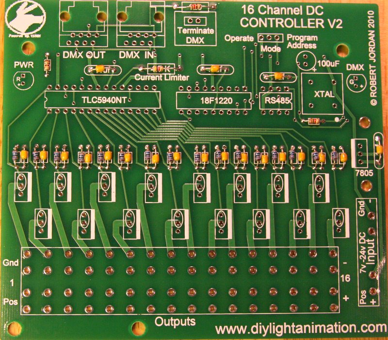
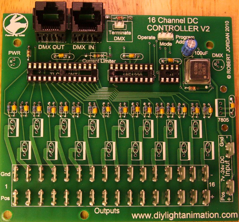
Install the 4 0.1uF ceramic capacitors as marked (3 near the top and 1 in the middle right). The ceramic capacitors are not polarized so orientation does not matter.
Install the 180 ohm (brown-gray-brown) resistor in the upper left corner. The orientation on all of the resistors does not matter, although you will end up with a cleaner looking build if you orient them in a consistent way.
Install the 1K ohm (brown-black red) resistor below the area marked XTAL.
Install the 120 ohm (brown-red-brown) resistor in the very upper middle area.
If you are doing the standard build and will be using the MOSFET's for high current operation, install the following:
Install the 16 3.0K ohm (orange-black-black-brown-brown) resistors in the marked locations across the middle of the PCB.
Install the 16 0.1uF ceramic capacitors as marked (across the middle).
Install the 4.7K ohm (yellow-violet-red) resistor in the location above the label "Current Limiter".
If, however, you plan to jumper where the ovals are marked and leave the MOSFET's off for constant current drive up to 100ma per channel, then:
Do NOT install the 16 3K resistor and 16 0.1uF capacitors.
Choose a resistor to match the current limit you need and install it in place of the 4.7K ohm resistor. The correct value for the current needed can be located in the datasheet for the TLC5940NT chip. Common currents are:
- 20 ma - Use 1.91K ohm.
- 100 ma - Use 380 ohm.
Solder and trim all excess leads.
That’s a lot of soldering so take a break. If you try to do too much in one sitting you will start making too many mistakes. Mistakes with soldering are costly in time.
STEP 2 - Installing the IC Sockets and Oscillator
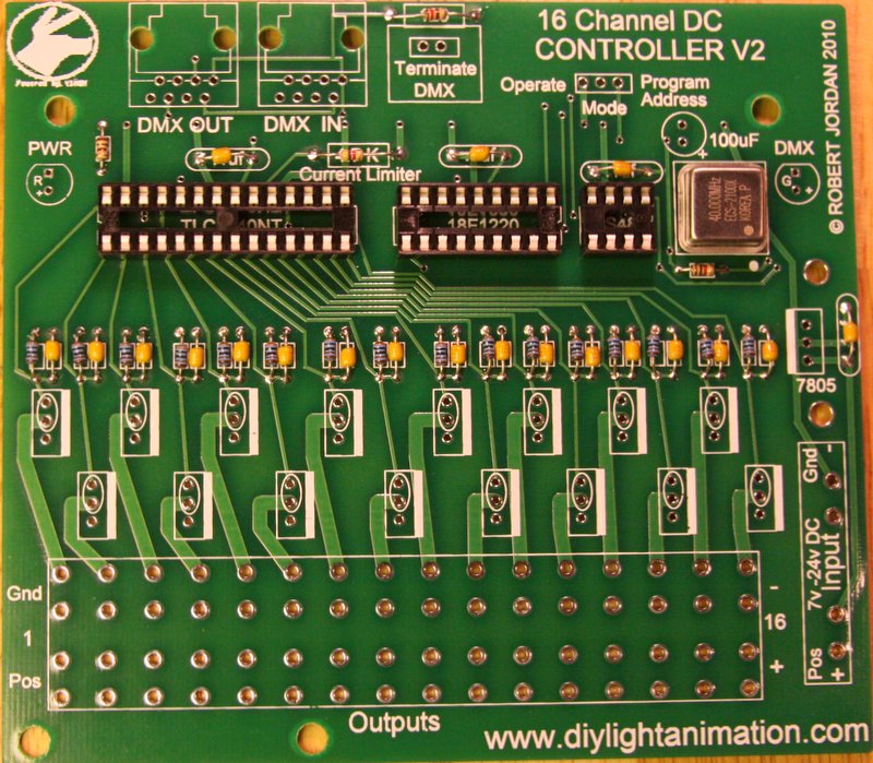
Install the 8 pin IC socket in the area labeled RS485.
Install the 18 pin IC socket in the area labeled 18F1220.
Install the 28 pin IC socket in the area labeled TLC5940NT.
Line up the notch on the sockets with the notched end of the drawings on the PCB and then solder all the pins.
Some sockets now come with slightly contoured pins that hold them in place in the PCB prior to soldering. If you do not have this kind of socket you will want to use a method to hold it in place while soldering. Everyone has their own way of holding the socket in. I like to turn the board over to the back and put the least amount of solder I can over one of the middle holes on one side of the socket. This allows you to put the pins of the other side of the socket through and hold the socket while pushing extremely easy. Then you heat that one hole on the back. When the solder melts the socket will drop in. remove the iron and it will cool and hold the socket in until you are done. Make sure to reheat this pin while doing the others to insure you have a good joint. Some people prefer to use tape to hold them in and some even super glue them on first and then solder. If you use tape then the painter’s masking tape is a good option as it does not leave any residue behind when it is removed. Make sure your socket is in the correct holes and that it faces the correct way and then solder the other pins in.
Locate the 40 MHz oscillator module. It is a shiny square unit with four pins. Install it in the area marked XTAL. The oscillator must also be oriented properly. You will notice a small dot on one corner of the component. This should line up with the white dot on the board. The corner with the dot will also have a square corner instead of rounded corners. Solder the four pins to the board.
STEP 3 - Installing the Spade Terminals
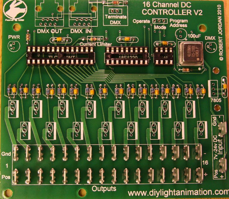
Install the quick fit spade terminals. Push each spade terminal into the 32 locations across the bottom. Then install two for power on the right side of the PCB. Flip over the board and solder them. Make sure you have good solder connections here.
STEP 4 - Installing the RJ-45 Connectors, Jumper Headers, Electrolytic Capacitor
Install the 2 RJ-45 connectors in the locations at the top labeled DMX OUT and DMX IN. They will snap in tight so make sure to align the small pins correct and then support the board as you push them in. It takes effort to snap them in so support the PCB when you do this. Some like to put the PCB on foam and do it where the foam allows it to support the PCB. Solder the 8 pins on both sockets
Install the round 100uf electrolytic capacitor. This capacitor is polarized and needs to be installed with the correct orientation. Make sure the black band marked “-“ is NOT on the side where the “+” is labeled on the board.
Install the 2 pin and the 3 pin jumper headers at the top of the PCB in the area labeled Terminate DMX and Mode.
Solder the capacitor and headers. Trim any excess leads.
You can store the two blue jumpers by slipping them onto one of the posts of each header.
STEP 5 - Installing the Red and Green LED's
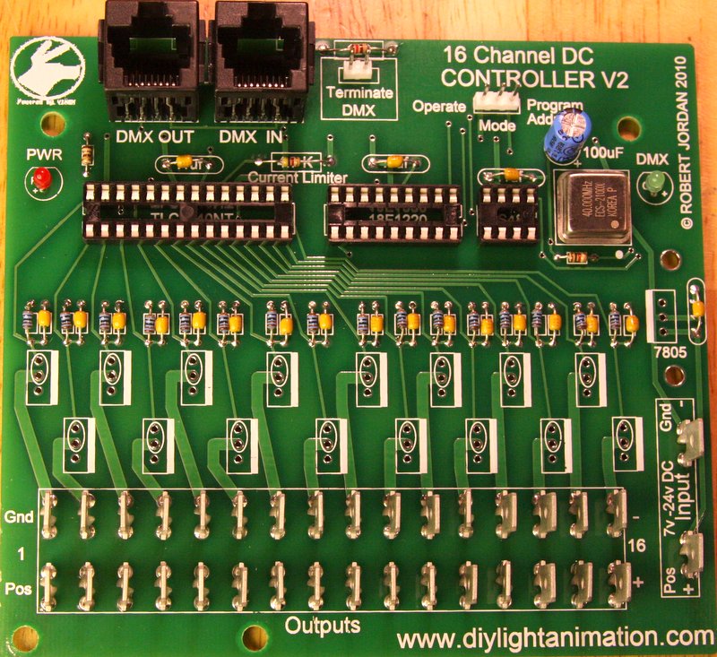
Install the red LED on the left side of the board below the PWR label. It is important to install the LED oriented properly. The LED will generally have one lead that is longer than the other. This is the positive (+) lead. The LED should be installed with the longer positive lead in the hole near the "+" label on the PCB.
Install the green LED on the right side of the board below the DMX label. Be sure to orient it properly as above.
Solder and trim the leads.
STEP 6 - Installing the MOSFET's and Voltage Regulator
If you will be doing the standard high current build:
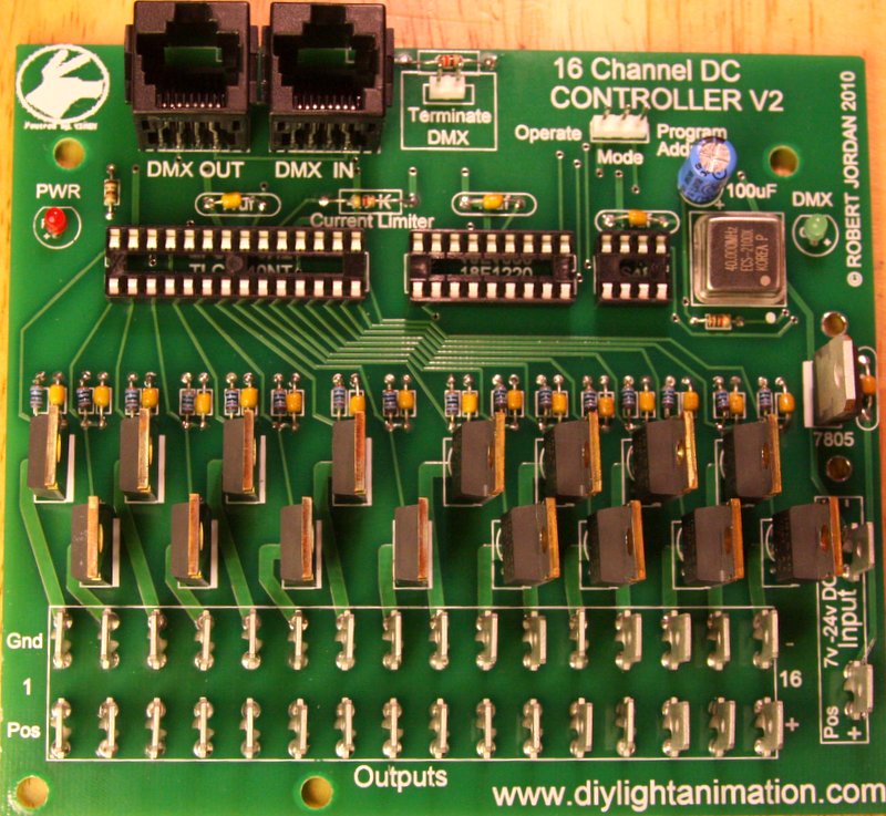
Install the 16 MOSFET's across the middle of the board. Make sure and face the flat metal side of the MOSFET's toward the bold white rectangle side of the outline on the board (facing right). Do not confuse the 16 MOSFET's with the one 7805 voltage regulator as they look identical.
If, however, you are going to use it in constant current mode:
Do NOT install the MOSFET's and, instead, install 16 jumpers in the areas that have the ovals around them.
Solder the MOSFET's or jumpers and trim the leads.
Install the 7805 voltage regulator in the middle right section of the PCB. Make sure and face the flat metal side of it toward the white rectangle side of the part outline on the board (left facing). Solder and trim the leads.
STEP 7 - Installing the Voltage Regulator Heat Sink
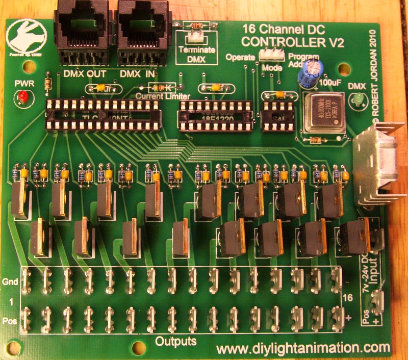
Install the metal heat sink onto the 7805 voltage regulator. It should be oriented so that the large flat side is facing left. Solder the two tabs of the heat sink.
STEP 8 - Installing the IC's
Install the TLC5940NT, 18F1220, and RS485 chips into their respective sockets. Make sure you align the notch on the end of the chip with the notch on the socket. Be very careful and do not bend any pins as they sometimes can be a challenge to insert straight. Take your time here and before pushing them in. Look over both sides to make sure all pins are started straight.
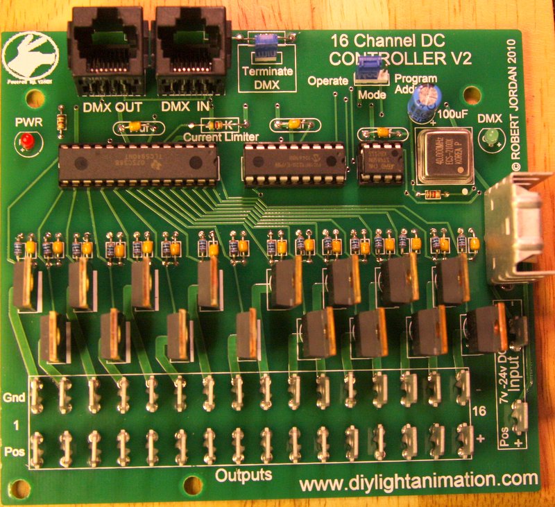
Congratulations, you have a finished building the Lynx MR16 V2 Controller!
You will need to feed the board from a regulated 7 to 24 volt DC power supply (12V is typical). Make sure the supply has the current capacity to handle the lights you are controlling. For example, the WireKAT 32 LED MR16 draw about .17 amps per lamp. Plan accordingly for your use.
Do not attempt to control more than 2.5 amps per channel from the MR16 controller. I also recommend you keep the total controller current under 35 amps if possible.
Programming and Operation
Programming the MR-16
The MR16 controller needs to be programmed for its starting DMX channel. This is the channel that output number 1 will be addressed by in the DMX data. If you want this controller to handle channels 80 through 95, for example, you would assign it the starting channel of 80.
To program the Lynx Controller/Dimmer.
- Note: For MR16/DC Controller, where it says turn power on or off, substitute that for connect/remove the negative power lead to/from the MR16
- Note2: Dongle DMX & Pixelnet Firmware - Require different software in order to set the start address
- Note2: DMX Firmware you can use RJ's Lynx Address Program or DMX Deck
- Note2: Pixelnet Firmware you can use Start Channel or xLights or your Sequence software with Pixelnet
Step 1 - Turn off power to controller and move jumper to program mode Leave Power OFF until Step 3
Step 2 - Use appropriate software (see Note2 above) and select address you need. Click on Program button
Step 3 - Turn on controller and count to 5
Step 4 - Turn off controller and move jumper back to operation mode Leave Power OFF until Step 6
Step 5 - Click Stop on the Lynx Address Program
Step 6 - Turn on controller and use your selected program to see if controller is now on the correct start address.
Either exit selected Program or go back to step 1 to program another controller
OPTIONAL Way if the above doesn't work - From RJ
Step 1 - Power up Controller.
Step 2 - Using selected program start to send the address you want.
Step 3 - With power ON carefully move the jumper to Program.
Step 4 - Count to 3 seconds.
Step 5 - Turn OFF the controller.
Step 6 - Put the jumper back to operate and power up controller to try/test.
It should now be set to operate on the channel you wanted. You can change it anytime and as often as you need. It will remember the address for at least 20 years with no power applied.
Operation
The MR16 is a DMX device and can be controlled from programs such as Vixen, Light-O-Rama, Light Show Pro, and others.
When using Vixen I recommend you set Vixen to “draw at 255 levels” instead of 0-100 levels. This will give you access to all 256 levels it provides and not limit it to just 100 steps.
To connect another DMX device to this one simply use a standard straight through Cat5 cable to go from the “DMX OUT” jack to the next device and connect it to its “DMX IN” jack.
- Original V1.0 Manual by RJ
- Updated V2.0 Manual by mokeefe
